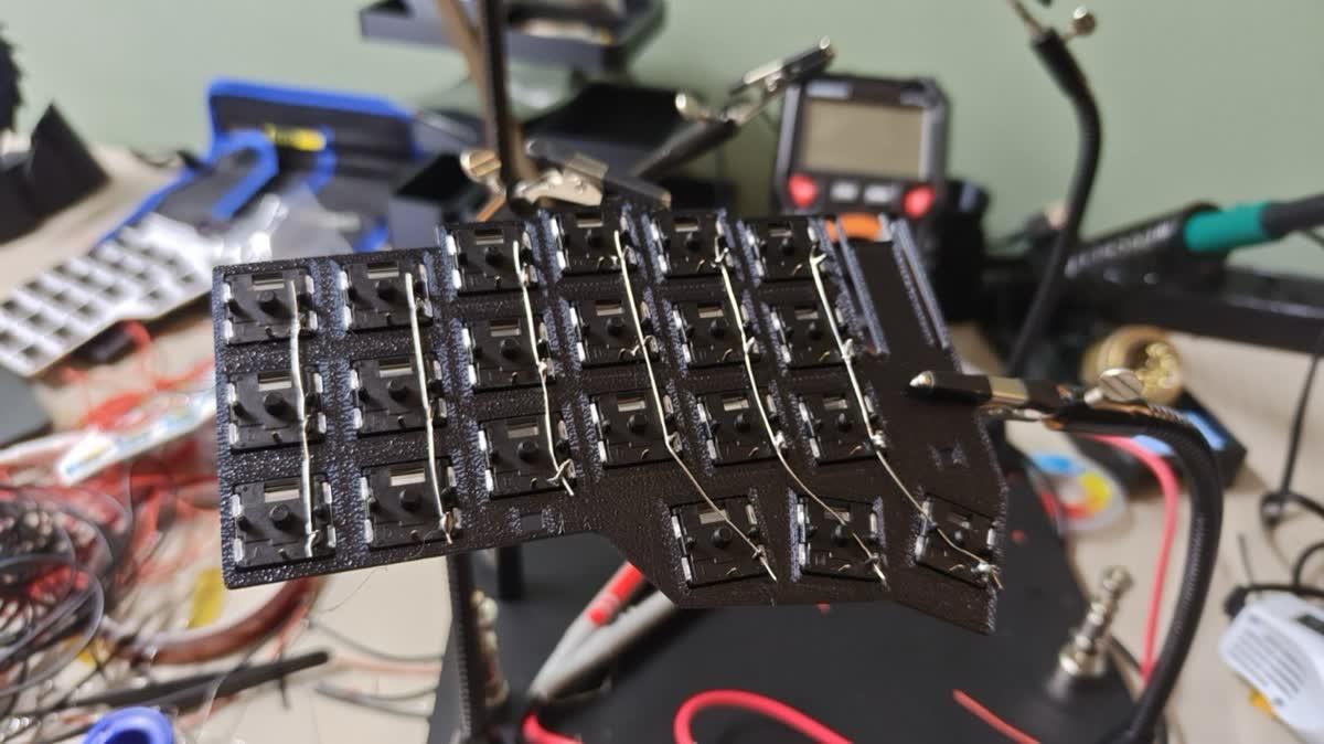
Part 2 of a series. Part 1 covers the first solder joint, the key grid and the first letters typed.
Day 2 was one long evening on 22 November that ran past 1 AM. It was not a full success.
Where things stand after day two:
- The new case works. The plate sits in it with no flex. Two small printed clips hold it. No screws.
- I rewired the left half from scratch with black switches. All 21 keys passed their tests.
- Two new controller boards would not start. I found the cause and fixed it in the firmware.
- Then one of those boards died while I was soldering it. So the left half has no working board in it right now.
- The right half's case is printed and its first wires are on.
Why the case had to change
Part 1 ended with a plan: put the controller board on top of the plate, in the empty corner, and make the case slim.
In the days after, I designed two versions of that. The first held the plate with snap hooks. The second let the plate slide into the case from one end, with a small door to lock it.
The snap-hook version I designed right after Part 1
Neither felt right. I did not like the door. It also failed once on the printer: it is a thin strip that prints standing up, and it came loose from the bed halfway through.
The bigger problem was flex. In both versions the plate only rested on its edges. Press a key in the middle and the plate bent down under your finger. A keyboard that sinks when you type feels cheap.
So I started again with two goals. The plate must not bend. And the whole thing should be as few parts as possible.
The new design: two parts and two clips
There are now only two printed parts, the plate and the case. Plus two small clip keys that lock them together.
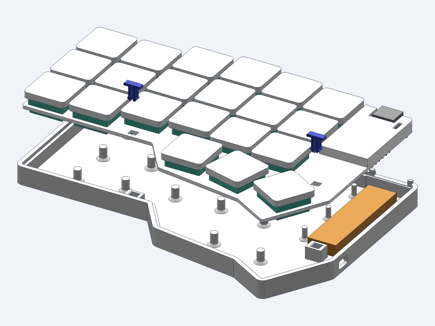 The plate, the clip keys and the case pulled apart. The orange block is the battery.
The plate is 1.35 mm thick. Choc switches clip into a plate 1.2 to 1.3 mm thick, and these already sat well in it. The board sits on top, in its own pocket in the corner.
The case is a thin tray drawn from the outline of the plate. The floor is flat. The old case was tilted, and the tilt cost 4 mm of height at one edge.
The plate drops in from above. It rests on a 1 mm ledge that runs all the way round the inside of the wall.
The important part is the posts. 20 small posts stand up from the floor and touch the underside of the plate. They sit in the gaps between the switches. The row wires also cross those gaps, near the key edges. So I mapped every path a wire could take under the plate, and moved each post just far enough to stay at least 0.3 mm clear of all of them.
The lock is a small flat T-shaped key. You push it down through a slot in the plate into a socket in the case floor, and it clicks. Its two legs bend in, then spring out under a sloped roof. The 45 degree slope means it prints without supports. It also means the key can come out again: lift one end of its head with a fingernail.
The whole half got much lower. From the desk to the top of the keycaps it went from about 18.5 mm to 13.5 mm.
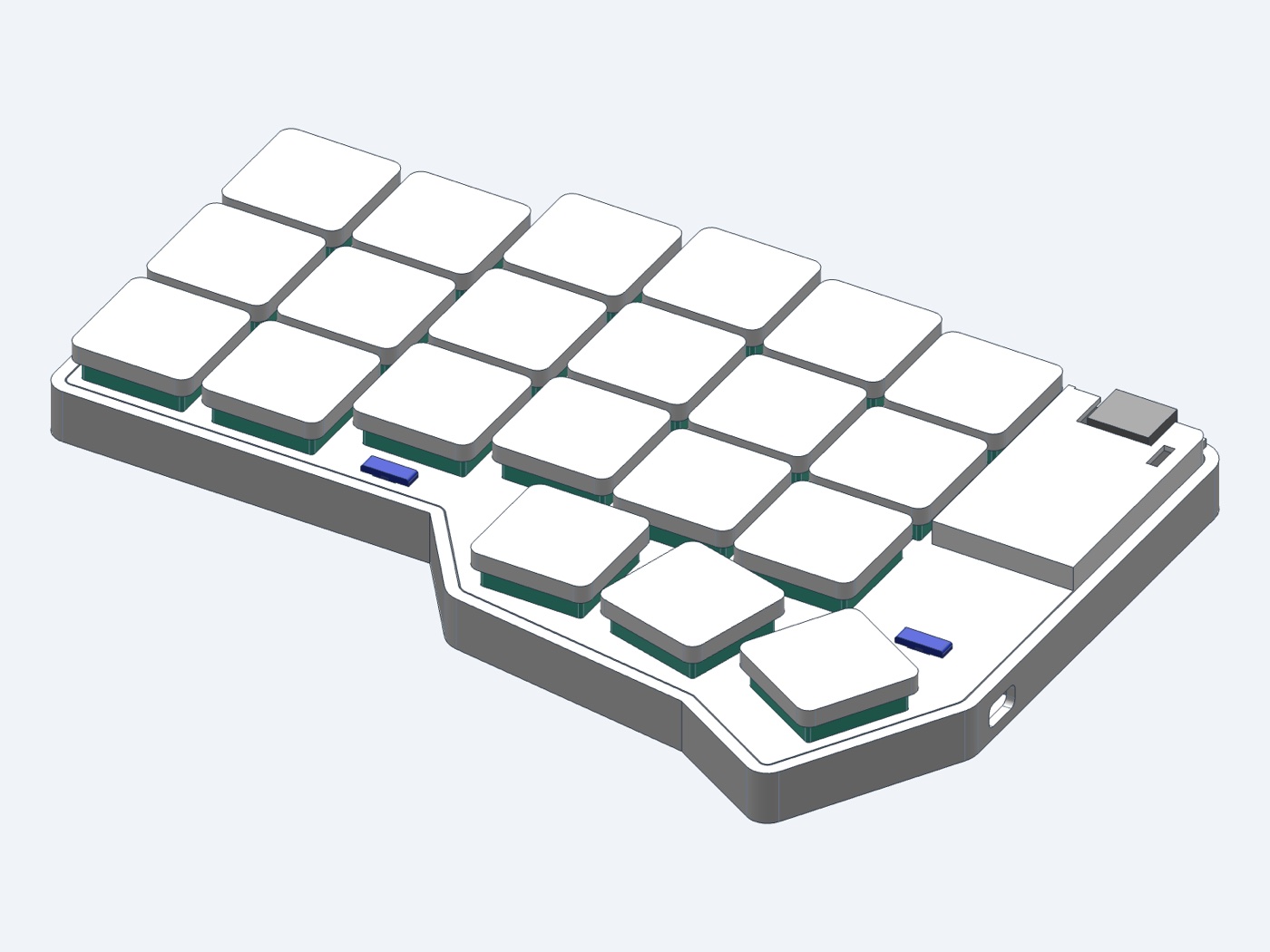 The new left half, put together on the computer
Testing it on the computer first
Each case print takes about 45 minutes. Each plate takes 30. A failed print costs time and plastic. A check on the computer takes seconds.
Fit checks
I wrote 18 checks that run on the 3D model every time it changes. A few of them:
- No part touches another part, even with every keycap pressed down 3 mm.
- The gap between the plate and the case wall is 0.2 mm all round.
- The plate sits on the ledge and the posts with no gap.
- The clip key has 0.07 mm of room in its socket, and it catches if you pull it up 0.2 mm.
- The USB-C plug fits without hitting the case.
All 18 passed before I printed anything.
Will the plate bend?
This is the check I cared about most. I ran a flex simulation.
The idea is simple. The computer covers the plate in about 17,000 points, joined into tiny triangles. It knows how stiff PLA plastic is. It knows where the plate is held up: the real ledge and post tops from the case model. Then it pushes on one key with 5 newtons. That is about ten times what a key needs to press down, so a hard press. It works out how far every point moves. Then it does the same for the next key.
To make sure the method was right, I first ran it on a plain square plate. That shape has an answer in textbooks. The simulation was off by 0.43%.
The results:
| Setup | Worst key sinks by |
|---|---|
| Plate held only by the edge ledge | 0.548 mm |
| Edge ledge plus 20 posts | 0.032 mm |
That is about 17 times less bend.
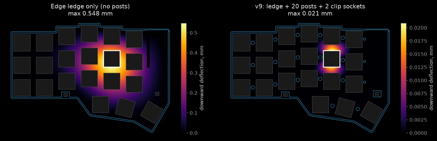 The same key pressed in both setups. Brighter means it sinks more. Left: edge only. Right: with the posts. Note the scales are very different.
Test pieces for the clips
A clip like this depends on a tiny gap between the key and its socket. Too tight and it won't go in. Too loose and it falls out. A printer can be off by a tenth of a millimetre, so I could not trust the number on paper.
So I printed a small test piece first. It has three sockets with gaps of 0.10, 0.15 and 0.20 mm, marked with 1, 2 and 3 notches. Next to it, a corner of the case with four posts, and a matching corner of the plate.
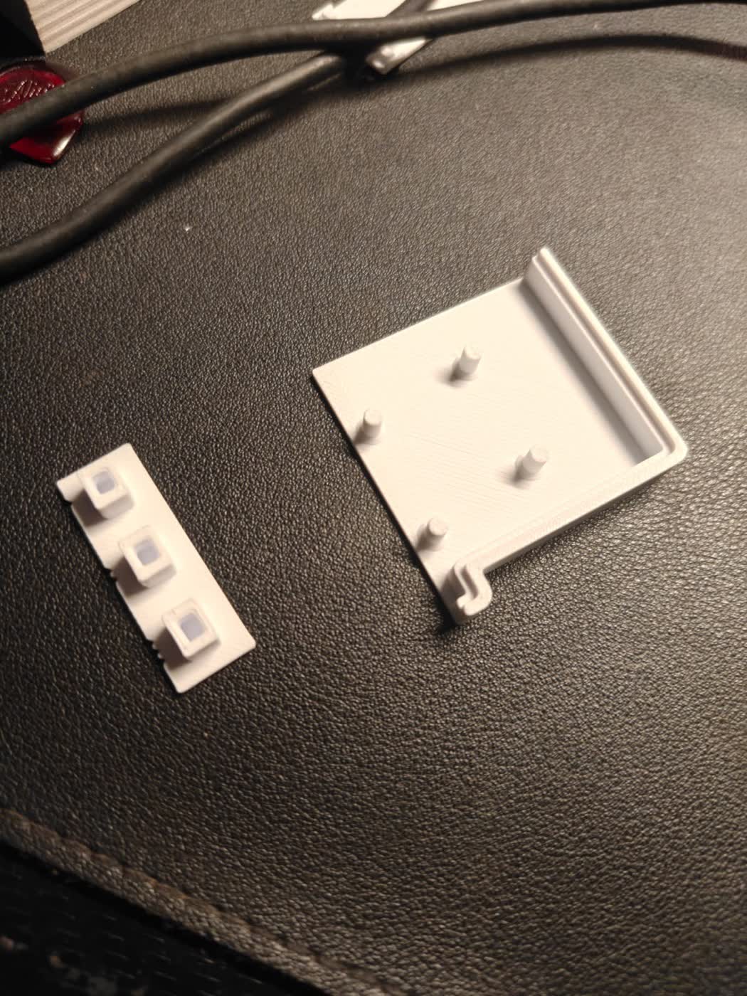 Test pieces: a strip with three clip sockets, and one corner of the case with its posts
All three keys clicked in, and all three came out with a fingernail. I kept the middle gap, 0.15 mm. If a later print comes out a little tight or a little loose, it still has room to work.
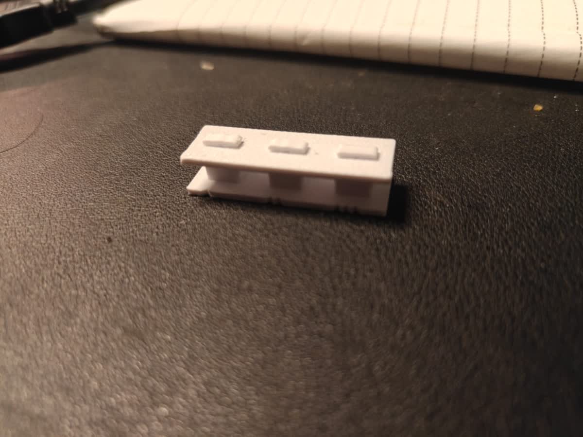 The clip test piece with all three keys clicked in
The case print
Then the real case. 45 minutes and 25 g of white PLA, with no supports.
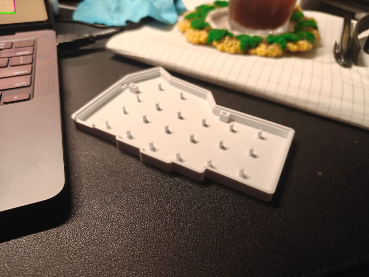 The new case. The small round posts hold up the plate.
A cover that slides on
The first version of the new plate had a fixed roof printed over the board. That meant the board had to slide in from the edge after it was soldered. I wanted it the other way round. Solder the board in place on an open plate, and put the cover on last. I also want to make other covers later.
So the plate got a pocket with a groove cut into each side wall. The cover slides into the grooves like a battery door. A small leg under the cover rides over a 0.5 mm bump on the plate and clicks into place. To take it off, lift the back end with a fingernail and slide it back.
I had tested these exact grooves earlier on a small test piece. All three gap sizes I tried slid on and held.
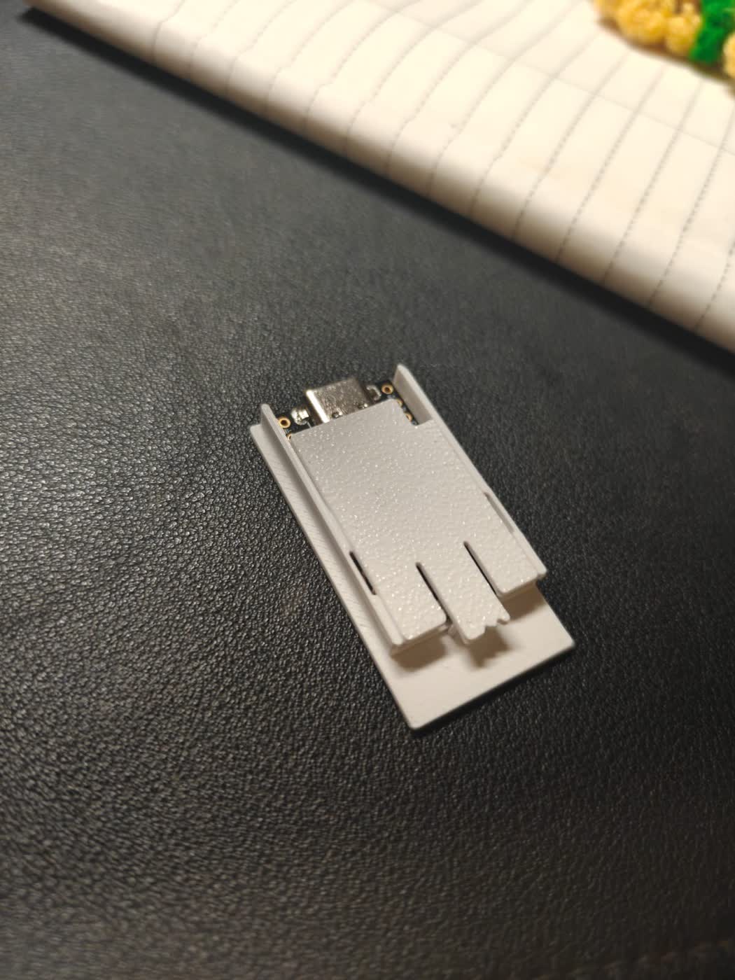 An earlier test piece: the board in its pocket, with a cover slid on. The USB socket stays open.
Plate in the case: no flex
The plate printed in 29 minutes. I dropped it into the case and pushed both clips in. They clicked.
Then I pressed down across the plate. No flex, just as the simulation said. It looks good and feels strong.
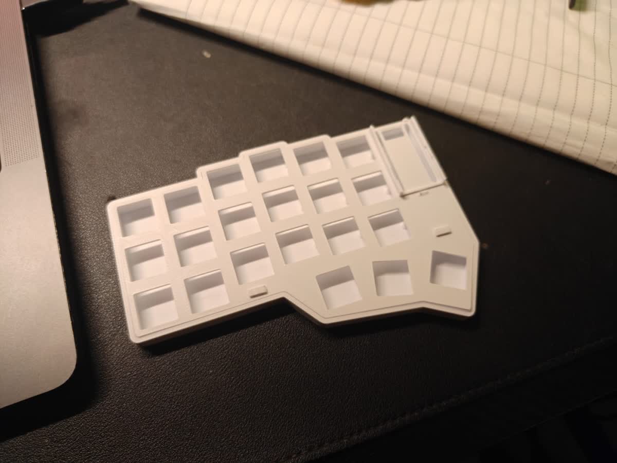 The new plate in the new case, both clips in. The board pocket is in the top right corner.
It was not perfect. Two opposite corners sat a little proud of the case. My best guess is that the plate twisted slightly as it cooled on the printer. Both clips sit on one line near the bottom edge, so nothing holds the top of the plate down.
I designed a fix: a third clip at the tip of the thumb keys, and a small tongue on the top-left corner that slides under the case wall. The same simulation says it closes both corners. It is not printed yet.
Rewiring the left half
The old wiring from Part 1 worked, but the board leads were a mess. I took everything apart and started again on the new plate, with black Choc switches this time.
Same method as before. Columns first, in bare copper wire. Then a diode on each key, with the striped legs chained into rows, and a piece of yellow heat-shrink at every spot where a row crosses a column.
This time I tested as I went. A beep test on each column. A diode test on each key. All 21 keys passed.
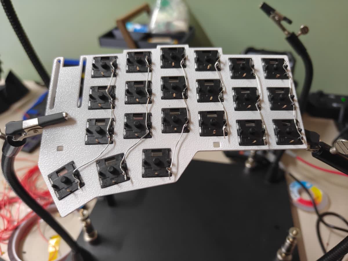 Columns done on the new plate
It went much quicker and looks much neater than the first time. Practice helps.
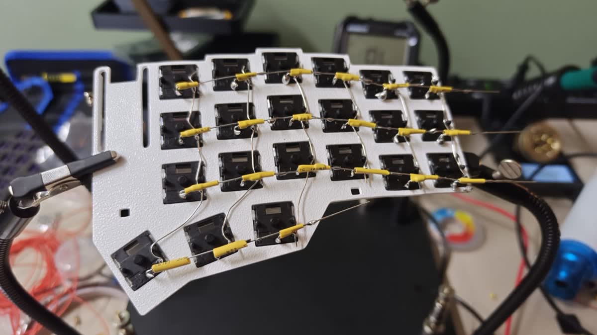 The full grid: columns, diodes and rows with a sleeve at every crossing
Then the board. I soldered a red lead to each pin I needed, with the board held in the helping hands.
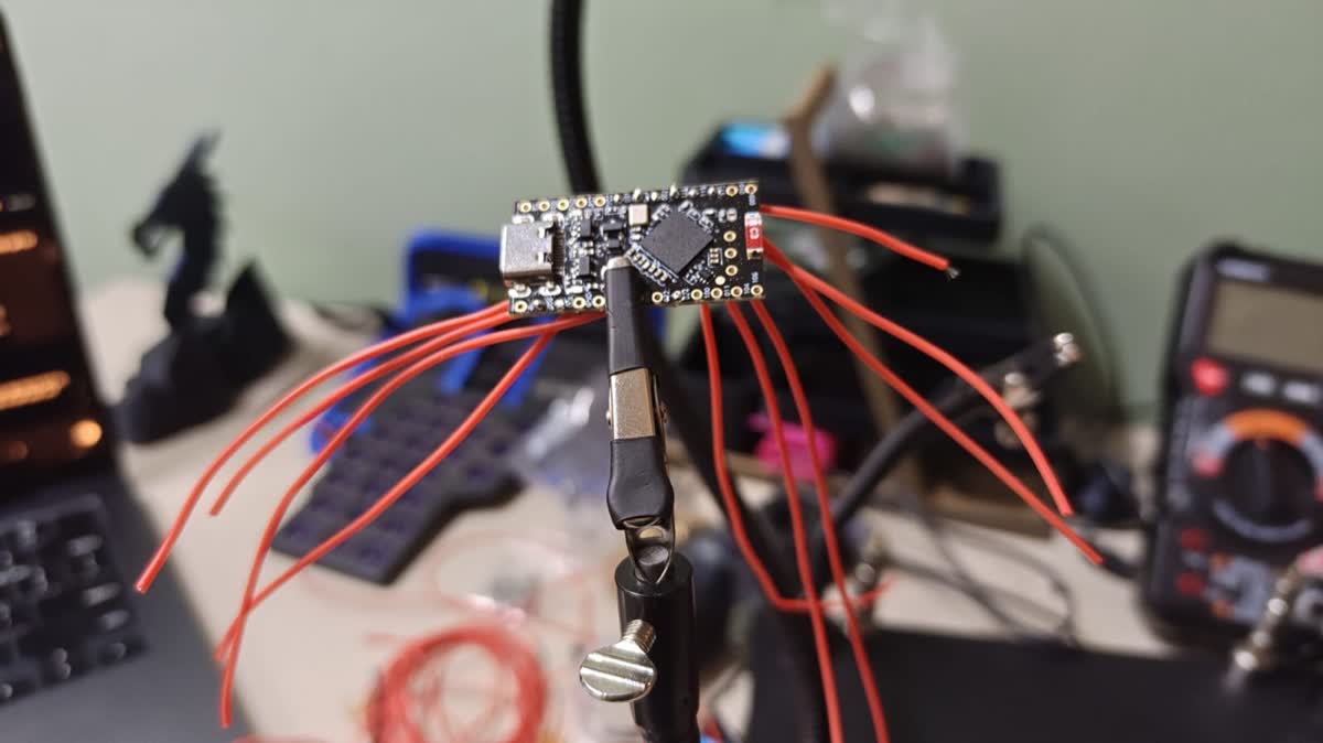 The board with its leads, before they go to the grid
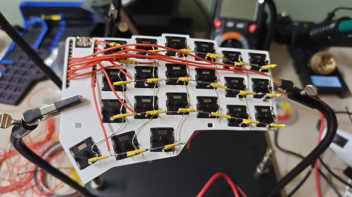 The board wired to the grid
One small thing from Part 1 came back. Last time I soldered the columns to the board in reverse order, and fixed it by reversing the column order in the firmware. This time I soldered them in the planned order. So that firmware fix had to be undone. One line again.
The boards that would not start
This is where the evening went wrong.
The old board stopped showing up
I flashed new firmware to the board from Part 1. After that, the Mac mostly did not see it. The blue light blinked fast, which means the board is waiting for firmware. But no drive appeared.
The cable was fine. My phone showed up on the same cable. So I put that board aside. It probably has a bad joint on its USB socket, which I will check later.
Two new boards that kept restarting
I took two new boards from the pack. Both took the firmware. Neither started. They kept falling back into update mode, over and over. The same file had worked on another board.
My first guess was the clock. Some cheap copies skip a small crystal that the chip can use to keep time. I changed the firmware to use the chip's own clock instead. That was not enough on its own.
The real cause was power. The chip has two ways to make its own power from the battery. One is a more efficient mode called DC/DC. It needs a couple of tiny extra parts on the board, called inductors. Some cheap copies leave them off. The current ZMK code turns DC/DC on. On a board without those parts, the power drops as soon as the chip starts, and it restarts. Then it tries again.
The fix was two lines in my board config. They turn DC/DC off and use the simpler mode. The new board came up at once and showed up on the Mac as "Corne HW".
Copying firmware on a Mac
One more thing I learned on the way. To flash a board, you copy a .uf2 file onto the drive it shows up as. On a Mac, a normal copy can add hidden extra data to the file, and the board can restart before the copy has fully finished. These two commands avoid both problems:
cp -X corne_handwired_left-nice_nano__zmk-zmk.uf2 /Volumes/NICENANO/
sync
cp -X copies the file without the hidden extra data. sync waits until everything is really written to the board.
The board that died
With the new board in, the left half typed every key except the thumb keys. The thumb row wire had come off. I also had to fix one loose column joint.
While I was soldering it back on, the board stopped. No red light. Nothing on USB. The reset did nothing. Only the blue charging light was on.
I checked for a short between the power pins and ground. There was none. Then I measured two pins with the multimeter:
- RAW, where USB power comes in: 4.15 V. So power was getting to the board.
- VCC, the 3.3 V the chip runs on: 0 V.
Between those two pins sits a small part called a regulator. It turns the USB and battery power into the steady 3.3 V the chip needs. That part was dead. Most likely I gave it too much heat, or the iron slipped while I worked on the pin next to it. That one is on me.
So I ended the night with a well-wired left half and no working board in it.
What I would do differently
Test every board on its own first
I found out two boards had problems only after they were wired in. That cost hours. My new rule, before any wire goes on a board:
- Plug it in bare. Tap the reset pin to ground twice.
- Flash the firmware with
cp -Xandsync. - Check it shows up as "Corne HW".
- Touch two pins together with tweezers and check it types. For example, pins 113 and 006 type R.
- Measure VCC to ground. It should read about 3.3 V.
Then test it again after soldering, and again after it goes into the case.
Two more lessons from the dead board. Keep the iron on each pad for 2 to 3 seconds, no longer. Stay well away from the regulator and the USB socket. And if a board goes dark, measure VCC first.
If the Mac sees nothing, try another board
If the board blinks in update mode, the cable is known to be good, and the Mac still shows nothing, swap in another board before you dig deeper. I spent too long on the old one.
Open wire slots
On this plate the wire slots under the board are closed at both ends. So every lead had to go up through the plate first, and then be soldered to the board sitting right above it. That is awkward.
The next plate has the slots open at the USB edge. I can solder the board to all its leads on the bench, where it is easy to see. Then I lower it into the pocket and the leads slide along the open slots to their pins. The new plate also has the third clip and the corner tongue. It passes all 60 checks on the computer. It is not printed yet.
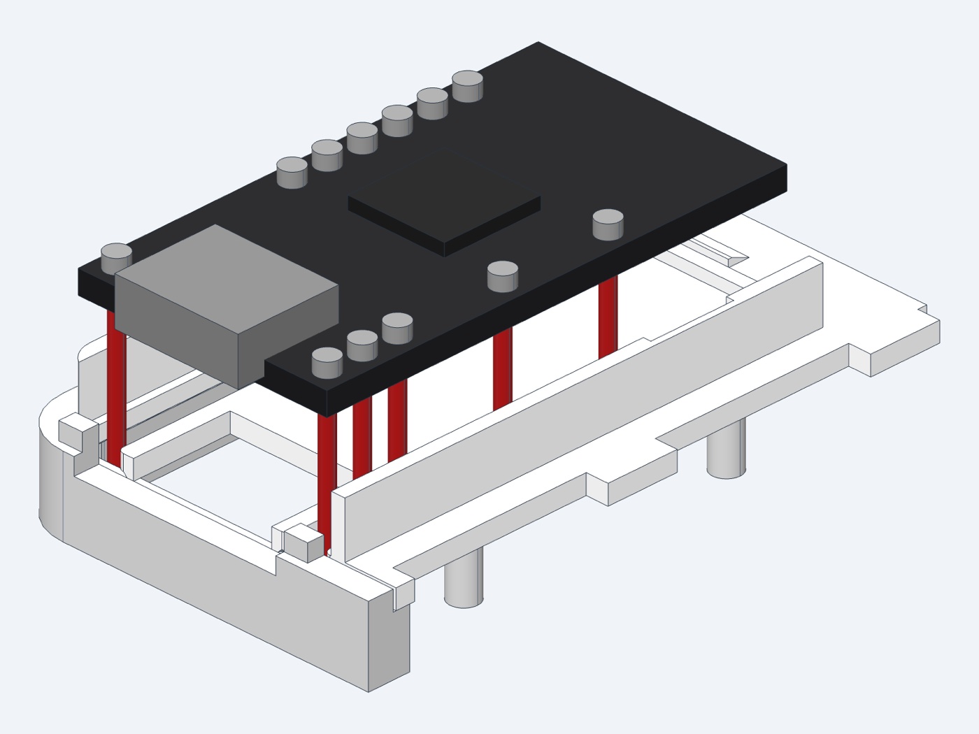 The next plate: the board is soldered first, then lowered into the pocket with its leads sliding into the open slots
The right half
The right half uses the same design, mirrored. The board itself is not mirrored. It is the same board, chip side up. So its two rows of pins swap sides, and the small window in the cover over the reset pins had to move across to match.
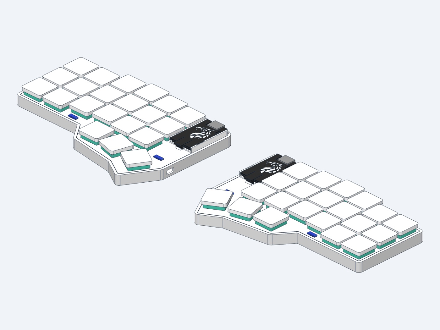 Both halves, side by side
I printed the right case in black and started its columns.
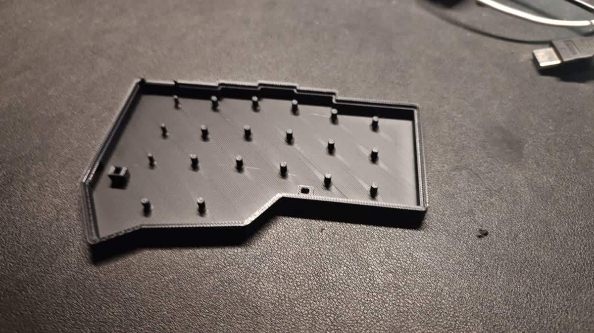 The right case in black
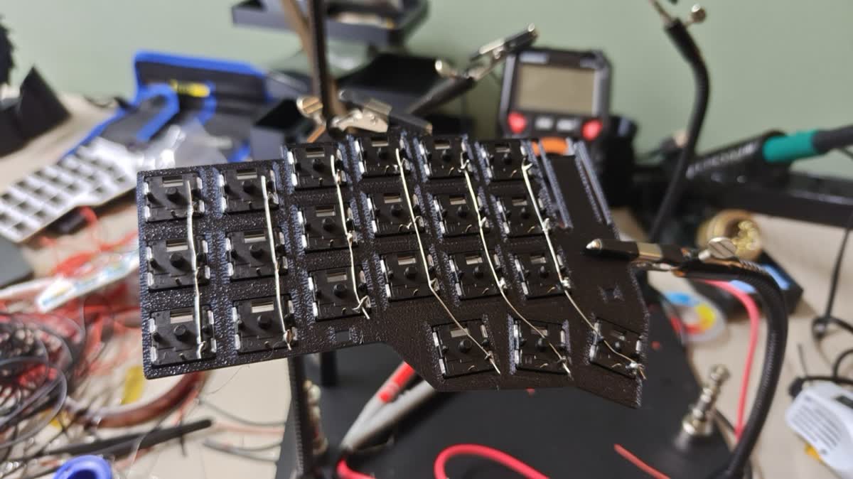 The right half's columns going on
Next
More iterations. Each one fixes something this round taught me.
- A plate that holds the board's pin headers. The headers press into slots in the plate, the board sits on top, and all the wires solder to the pins underneath, away from the board.
- Socket strips in those same slots, so a board just pulls off. Two boards died this week. Swapping one should take a minute, not an evening of desoldering.
- A thin plate under the switch plate that holds a hot-swap socket for every switch. The wires go to the sockets, and switches push in and pull out with no soldering.
- A third clip at the thumb keys, and a tongue at the top-left corner, so the plate sits flat everywhere.
- More boards are on order, and each one gets tested bare before any wire touches it.
I have also drawn a proper circuit board for both halves, so a future version needs no hand wiring at all. I will not order it until the hand-wired version fully works.
Next: Part 3, a working pair of halves, I hope.